
Fibre Positioner
Each of the 32,000 MOS optical fibres will be located onto the astronomical target of interest using a fibre positioner module. Each fibre positioner is a small robotic arm that can move the optical fibre from one place to another, very accurately. The size of the MOS focal plane requires that the centre-to-centre separation between fibre positioners needs to be approximately 7 mm to fit all 32,000 positioners within the WST’s field of view.
The WST project is investigating four different types of fibre positioner technology to decide which is best suited to the WST requirements. Two types use novel technology of low TRL and the second two use heritage technology of high TRL.
The first type of positioner being investigated uses two axes of rotation to move the fibre and is known as a Phi-Theta actuator. The use of Phi-Theta fibre positioners is already demonstrated on existing MOS instruments such as DESI and PFS. The second positioner concept being investigated uses tilting spines technology, as used on 4MOST. The third positioner concept being investigated is Phi-R concept with one axis of rotation and one linear movement. There is also a novel fourth design being investigated, which uses a tripod-like structure with three axes of movement. The three axes design potentially has the largest patrol field, and this can provide operational advantages.
Focal plane diagram with triangular positioner modules.
Credits: the WST consortium
Optical fibres
The WST will use optical fibres to relay light from the telescope’s focal plane to the multiple-object spectrographs. This is a well-established observing technique already successfully in use on various multiple-object spectrographs such as DESI and 4MOST. The FoV on sky of each optical fibre will be 1.0 arc-seconds. The core diameter of the optical fibre is approximately 200 μm. The optical fibres are required to efficiently carry light over the full wavelength range (370 nm to 930 nm). To provide high efficiency, the fibre length needs to be kept to a minimum: for this reason, the multiple-object spectrographs will be positioned as close to the telescope as possible. This is particularly important at short wavelengths, below 400 nm, where the transmission of optical fibres is affected by internal absorption within the fibre.
For installation and maintenance purposes, the optical fibres will include connectors at strategic points along their length. The WST instrumentation team is investigating new fibre connector technology that will enable high-efficiency coupling of many fibres simultaneously. The fibre connectors might also be designed to have provision to inject calibration light directly into the fibre.
Low-Resolution Multi Object Spectrograph
The low-resolution multi-object spectrographs will enable the simultaneous observation of 30,000 targets, at a spectral resolving power R > 3,000, over the full wavelength range of 370 nm to 930 nm.
Several optical design concepts for the MOS-LR spectrograph are currently under evaluation. One of these uses a conventional optical layout with an off-axis slit and collimator. The collimated beam is separated into four wavelength channels by three dichroic beam splitter filters. Each channel has a transmissive disperser, a refractive camera, and a detector. In total 58 MOS-LR spectrographs would be needed to provide the required multiplex.
Another MOS-LR optical design uses a Schmidt type camera. This design is notable for having fewer optical surfaces and hence potentially lower cost.
The Schmidt style camera design does however make the detector packaging more difficult than the refractive camera design already described.
Picture courtesy of Will Saunders. Optical ray-trace diagram of a proposed design of spectrograph for the MOS-LR. The entrance slit is located at lower centre and sends light towards a collimator mirror on the right. The collimated beam is incident on two dichroic beam-splitter filters that separate the beam into three wavelength channels, and a third dichroic beam-splitter gives a fourth wavelength channel. Each channel has a transmissive disperser, a refractive camera, and a detector.
High-Resolution Multi Object Spectrograph
The high-resolution multi-object spectrograph will allow the simultaneous observations of spectra of 2,000 objects, with a spectral resolving power of R = 40,000, over four wavelength ranges (passbands). Achieving high spectral resolving power on a 12-m class telescope represents a considerable optical design challenge.
The spectrograph is fed by seven small fibres per object rather than one large fibre. This approach enables the spectrograph optics to be kept to a size that can be more easily manufactured. The MOS-HR would therefore be fed by 14,000 fibres each with a diameter of approximately 80 μm. In total 8 spectrographs would be needed to observe all fibres.
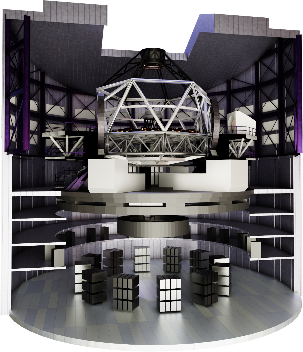
Picture courtesy of Simone D’Auria (INAF), Gaston Gausachs (ANU) and Maria Cristina Fortuna (INAF). Picture of a design concept for the high-resolution multiple object spectrograph modules located on the rotating floor of the telescope structure. There are three modules, coloured blue and grey, measuring width 3.3 m by height 3.3 m by 4.4 m length. Each module contains two separate spectrographs co-located on a central vertical optical bench. The enclosure of each module is light tight and provides thermal insulation to minimise temperature variations of the spectrograph.
Integral Field Spectrograph
The F of the IFS will be extracted from the centre of the MOS field of view and sent via an optical relay system to the IFS room at the base of the telescope structure. Upon reaching the IFS focal station the 3 x 3 arc-minutes squared field of view will be sliced into smaller sections by the first stage image slicer optical system. This will direct the beams to a second stage image slicer and finally the beam will be directed into the many integral field spectrographs. Each spectrograph will measure the full wavelength range 370 nm – 930 nm at a spectral resolving power of R > 3,000.
The WST IFS optical design, with different levels of image slicing, is based on heritage from the MUSE instrument on the ESO VLT.
The large number of spectrographs needed for the IFS is an interesting design challenge requiring simplification where possible – hence the investigation of the use of curved detectors to simplify the optical design. Mass production techniques for the spectrographs, the image-slicers and detector cryostat sub-systems are being investigated.
Advanced Technology
The WST project has identified, and is investigating, various advanced technologies that will make the instruments easier to construct and provide improved performance.
These technologies are detectors, cryostat vacuum vessels, and dispersers.
Calibration
The WST will have a calibration system capable of illuminating the instruments with a variety of light sources to provide different calibration functions. It is a requirement that calibration activity takes place during the day, and the need for nighttime calibration shall be kept to a minimum, thereby maximising the overall survey efficiency of the WST.
The WST calibration system will provide the following calibration functions for each spectrograph: wavelength calibration, flat-field and throughput calibration, and detector calibration. For the MOS-LR and IFS wavelength calibration will be provided by illuminating the telescope or instrument with spectral calibration lamps. A combination of lamps, such as Argon and Neon, will be used to provide enough spectral calibration wavelengths to accurately calibrate the spectrograph.
For the MOS-HR this approach may not be sufficient to achieve the required calibration accuracy. It is likely a light source with a larger number of calibration wavelengths may be needed. The use of laser frequency combs, or hollow cathode lamps with additional spectral wavelengths is being investigated.
Flat-field and throughput calibration will be done using a black body or continuum type light source of well-known spectral characteristics, such as a quartz tungsten halogen lamp.
The best method for illuminating the WST instruments with calibration light is currently under study. One option is to illuminate the entire telescope aperture via a 14 m dome screen. This option has the advantage of illuminating the entire telescope pupil, but it will be difficult to ensure the pupil is uniformly illuminated. An alternative option is to install light sources onto the telescope structure which directly illuminate the telescope’s primary mirror. This option does not provide uniform pupil illumination but provides more efficient coupling of light between the source and instruments. For the IFS there is a further option to inject calibration light into the IFS within the relay optics between the telescope and the IFS entrance focal surface.
Each spectrograph wavelength channel will be fitted with an LED light source, or similar, to provide direct illumination on the detector. This will enable monitoring of detector performance characteristics such as pixel response variations.
The MOS spectrographs will also be fitted with internal light sources to back illuminate the optical fibres. Back illumination of the fibres is necessary to allow the position of the end of each fibre to be seen and measured by the metrology system. The metrology system is an essential tool in ensuring each fibre is correctly positioned relative to the MOS focal surface’s coordinate system.
Back illumination of the optical fibres for positioner metrology purposes will likely be a calibration function that is needed during nighttime observations.
Future Developments
Whilst designing the WST instrumentation consideration is being given to future upgrade options. For example, the optical train of the telescope and fibres is being designed to be able to be used both in visible and a near-infrared wavelengths. This will enable a future upgrade option to near-infrared MOS and IFS capability.
Another potential future upgrade is the replacement of existing optical fibres, and their positioners, to versions equipped with miniature integral field unit fibre bundles. This would enable future MOS IFU capability.

The instruments
Issue #1 The WST Chronicle